
Climatic and Environmental Wind Tunnels
The FKFS operates three climate test benches with different performance ranges, which can be used for a wide variety of tests. These can be used, among other things, for thermal management and climate comfort, contamination investigations, as well as for performance measurements and component function tests. Depending on the test bench, there are different options for controlling air temperature, humidity, and irrigation, allowing flexible adjustment for customer-specific test scenarios.
The Climatic Wind Tunnel and the Thermal Wind Tunnel are Göttingen type wind tunnels including powerful 2-axis dyno test benches. Here, a wide range of different full-vehicle tests can be conducted independently of season and weather conditions, and driving tests can be realistically simulated. While the Climatic Wind Tunnel is primarily used for thermal tests in normal to hot temperature ranges, the thermal wind tunnel allows for the investigation of all aspects of rain simulation and waterproofing.
The climate chamber can be used in a temperature range from −35 °C to 55 °C and, taking into account sun simulation, can be used for investigations of interior comfort and air conditioning.


Contact
Ph.: +49 711 685-67615
Applications
Thermal Management

- Cooling circuit design and testing
- Heat protection investigations
HVAC Testing including Solar Load

- Cool Down Tests
- Shading Measures
- Thermal Comfort
Winter Testing
- Window Defrost
- Heat Up
- Window Defog
- Cold Start
- Thermal Comfort
Driving Performance

- Steady-state and drive cycle testing
- Power train durability tests
- Trailer-tow operation
Weathering

- DIN 75 220
- AECPT-300
Brake Performance

- Temperature induced brake fading
- Water induced brake fading
- Brake performance test (cylcle/downhill)
- Brake response characteristics
Water Management

- Air intake, clean-air path
- Water ingress
- Corrosion protection
- Imperviousness of components
- Sealing performance
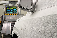
Vehicle Soiling

- Foreign and self soiling
- Sensor contamination
Visibility and View

- Wiper functionality
- Wiping quality
- Water pullback and overspray
Technical Data Thermal Wind Tunnel
| Nozzle | Small nozzle | Large nozzle |
| Plenum length | 13.8 m | 15.8 m |
| Nozzle area | 4 m² | 6 m² |
| Wind speed | 250 km/h | 200 km/h |
| Fan power | 1 MW | |
| Cooling capacity CWT | 1.6 MW | |
| Temperature range | 10 bis 50 °C | |
| Rain Water Simulation | 3 separated circuits with a total flow rate of 6000 l/h | |
| Dyno | Front | Rear |
| Max. traction force | ±20 kN | ±20 kN |
| Max. continuous power | 300 kW | 500 kW |
| Wheel base | 1.85 bis 5.2 m | |
| Max. speed | 300 km/h | |
| Max. axle load | 10 t | |
| Charging infrastructure | CCS2 22 kW AC | |
Technical Data Climatic Wind Tunnel
| Nozzle | Car | Truck |
| Plenum length | 14.3 m | 15.8 m |
| Nozzle area | 4.7 m² | 12 m² |
| Wind speed | 265 km/h | 135 km/h |
| Fan power | 1.3 MW | |
| Cooling capacity CWT | 2 MW | |
| Temperature range | 10 to 55 °C | |
| Rel. Humidity range | 10 – 90 % | |
| Solar load simulation area | 6 x 2.5 m | |
| Solar load range | up to 1200 W/m² | |
| Dyno | Front | Rear |
| Max. traction force | ±13 kN | ±26 kN |
| Max. continuous power | 300 kW | 450 kW |
| Wheel base | 2.3 to 6.9 m | |
| Max. speed | 280 km/h | |
| Max. axle load | 7 t | |
| Charging infrastructure | 322 kW at 920V / 140 kW at 400V CCS1 and CCS2 22 kW AC | |
Technical Data Climatic Chamber
| Nozzle | |
| Size | 12 x 5 x 5 m |
| Nozzle area | 0.48 m² |
| Wind speed | 120 km/h |
| Temperature range | −30 to 55 °C |
| Cooling capacity | 30 kW (−30 °C) or 110 kW (−5 °C) |
| Heating power | 50 kW |
| Rel. Humidity | 10 – 90 % |
| Solar load simulation area | 6 x 2.5 m |
| Solar load range | 500 – 1100 W/m² |
| Dyno | |
| Max. traction force | 6 kN |
| Max. continuous power | 260 kW |
| Max. speed | 200 km/h |
| Max. axle load | 2.5 t |
| Max. axle load chamber floor | 13 t |
| Charging infrastructure | 22 kW AC |